Parts Needed:
Audio & Cruise Switches w/Harness - 36770-SNA-A12
Brake Pedal Switch - 36750-SMA-013
1 Teal 10 Pin Connector For Distribution Block If Your Distribution Block Does Not Have One Already. My Own Did Not Have One. (Junkyard Is Your Friend On This One, Or Buy A Used Harness From eBay)
6 Clockspring Connector Pigtails, 3 Tachometer Connector Pigtails, 8 Distribution Block Connector Pigtails, 2 Brake Pedal Sensor Pigtails (The Smaller Ones Not The Bigger Ones) 2 20 Pin Radio Connector Pigtails, 1 MICU Rear Connector Q Pigtail & 1 ECU Pigtail (Honestly The Junkyard Is Your Friend. I Ordered a used dash harness for the majority of the pigtails and cut the ECU pigtail out of a parts car to complete this DIY)
These Were The Colors Used For The Wires In An 08 Civic EX (That Was Already Equipped With These Features) That I Was Referencing On How To Route The Wires, But You Can Use Any Color Wires You Want.
Let's Start With The Audio Controls Since It's Easier To Do.
Wiring Needed For Audio Controls:
Clockspring To 20 Pin Radio Connector:
Run The Brown & Pink Wires From The Clockspring Connector Slots 3 & 4 (Respectively) To the Radio 20 Pin Connector Slots 6 & 7 (Respectively).
![Image]()
And That's It For The Audio Controls!
Now Let's Move On To The Cruise Control.
Wiring Needed To Be Done For Cruise Control:
ECU To Brake Pedal Switch:
Run A Brown Wire From The ECU Connector A Slot 39 (You Will Have To Remove The Yellow Plug As Shown To Install The Pigtail) To The Brake Pedal Switch Connector Slot 3
![Image]()
You Will Need To Remove The Driver (Left) Side Fender And Run The Wire Through The Hood Latch Pull Wire Grommet. I Used These OEM Harness Zip Ties To Clean Everything Up
![Image]()
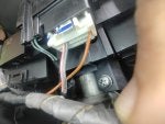
Brake Pedal Switch To Rear Of MICU:
Run A Yellow Wire From The Brake Pedal Switch Connector Slot 4 To Rear Of The MICU Connector Q Slot 2
![Image]()
Clockspring To Distribution Block:
Run The Grey, Red, Yellow, Light Orange & Teal Wires From The Clockspring Connector Slots 1, 2, 7, 8 & 9 (Respectively) To The Distribution Block
![Image]()
The Red Wire Goes To Teal 10 Pin Connector (Right Side Of 10 Pin Grey Connector) Slot 10 and the Grey, Yellow, Light Orange & Teal Wires Go To Grey 10 Pin Connector (Right Side Of White 22 Pin Connector) Slots 8, 5, 7 & 3 (Respectively)
![Image]()
Clockspring To Ground Point:
I Didn't Get A Photo Of It, But I'll Add It Later On If I Remember. Run A Black Wire From The Clockspring Connector Slot 6 To The Ground Point Behind Steering Wheel Next To Steering Column On Left Side.
- INSTRUCTIONS - As You're Laying Down Under The Driver (Left) Side Dash, With Your Head Facing The Front Of The Car And You Looking Up At The Steering Column, The Factory Under Dash Harness Ground Location Is On The Right Side Of The Steering Column On A Metal Plate.
Tachometer To Distribution Block:
Run The Yellow, Teal & Light Orange Wires From Tachometer Connector Slots 9, 10 & 11 (Respectively) To The Distribution Block White 22 Pin Connector (Right Side Of White 6 Pin Connector) Slots 5, 20 & 10 (Respectively)
![Image]()
And That's it For The Cruise Control!
Any questions feel free to ask!
Audio & Cruise Switches w/Harness - 36770-SNA-A12
Brake Pedal Switch - 36750-SMA-013
1 Teal 10 Pin Connector For Distribution Block If Your Distribution Block Does Not Have One Already. My Own Did Not Have One. (Junkyard Is Your Friend On This One, Or Buy A Used Harness From eBay)
6 Clockspring Connector Pigtails, 3 Tachometer Connector Pigtails, 8 Distribution Block Connector Pigtails, 2 Brake Pedal Sensor Pigtails (The Smaller Ones Not The Bigger Ones) 2 20 Pin Radio Connector Pigtails, 1 MICU Rear Connector Q Pigtail & 1 ECU Pigtail (Honestly The Junkyard Is Your Friend. I Ordered a used dash harness for the majority of the pigtails and cut the ECU pigtail out of a parts car to complete this DIY)
These Were The Colors Used For The Wires In An 08 Civic EX (That Was Already Equipped With These Features) That I Was Referencing On How To Route The Wires, But You Can Use Any Color Wires You Want.
Let's Start With The Audio Controls Since It's Easier To Do.
Wiring Needed For Audio Controls:
Clockspring To 20 Pin Radio Connector:
Run The Brown & Pink Wires From The Clockspring Connector Slots 3 & 4 (Respectively) To the Radio 20 Pin Connector Slots 6 & 7 (Respectively).
And That's It For The Audio Controls!
Now Let's Move On To The Cruise Control.
Wiring Needed To Be Done For Cruise Control:
ECU To Brake Pedal Switch:
Run A Brown Wire From The ECU Connector A Slot 39 (You Will Have To Remove The Yellow Plug As Shown To Install The Pigtail) To The Brake Pedal Switch Connector Slot 3
You Will Need To Remove The Driver (Left) Side Fender And Run The Wire Through The Hood Latch Pull Wire Grommet. I Used These OEM Harness Zip Ties To Clean Everything Up
Brake Pedal Switch To Rear Of MICU:
Run A Yellow Wire From The Brake Pedal Switch Connector Slot 4 To Rear Of The MICU Connector Q Slot 2
Clockspring To Distribution Block:
Run The Grey, Red, Yellow, Light Orange & Teal Wires From The Clockspring Connector Slots 1, 2, 7, 8 & 9 (Respectively) To The Distribution Block
The Red Wire Goes To Teal 10 Pin Connector (Right Side Of 10 Pin Grey Connector) Slot 10 and the Grey, Yellow, Light Orange & Teal Wires Go To Grey 10 Pin Connector (Right Side Of White 22 Pin Connector) Slots 8, 5, 7 & 3 (Respectively)
Clockspring To Ground Point:
I Didn't Get A Photo Of It, But I'll Add It Later On If I Remember. Run A Black Wire From The Clockspring Connector Slot 6 To The Ground Point Behind Steering Wheel Next To Steering Column On Left Side.
- INSTRUCTIONS - As You're Laying Down Under The Driver (Left) Side Dash, With Your Head Facing The Front Of The Car And You Looking Up At The Steering Column, The Factory Under Dash Harness Ground Location Is On The Right Side Of The Steering Column On A Metal Plate.
Tachometer To Distribution Block:
Run The Yellow, Teal & Light Orange Wires From Tachometer Connector Slots 9, 10 & 11 (Respectively) To The Distribution Block White 22 Pin Connector (Right Side Of White 6 Pin Connector) Slots 5, 20 & 10 (Respectively)
And That's it For The Cruise Control!
Any questions feel free to ask!